What was Project Emily?
Project Emily brought American-built Thor intermediate-range ballistic missiles to Britain as an interim nuclear deterrent. Sixty missiles were distributed among twenty RAF stations, with three emplacements at each. Their targets lay in the Soviet Union: they were part of the wider nuclear confrontation, not weapons positioned to strike Cuba.
The agreement emerged from the 1957 Bermuda meeting between Harold Macmillan and Dwight Eisenhower. Britain was developing its own Blue Streak missile, but that programme could not provide an immediate operational force. Thor offered a way to deploy a land-based ballistic missile sooner, alongside the RAF’s bombers.
Sources for this passage: [1] [2]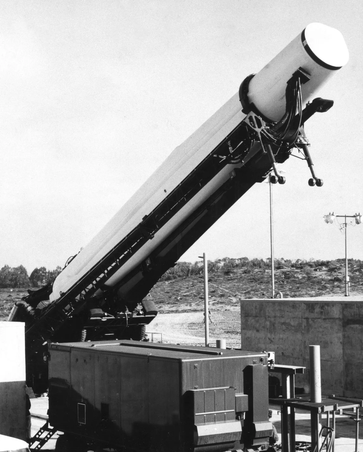


The missile: a rocket, not an aircraft
Thor was an intermediate-range ballistic missile, or IRBM. A rocket engine accelerated it onto a trajectory towards its target; it did not cruise through the atmosphere like a bomber. At roughly 20 metres tall, it was a substantial piece of machinery even before its transporter, fuel system and control equipment were counted.
The missile used a kerosene-based fuel and liquid oxygen. The oxygen was the oxidiser that allowed the engine to burn fuel without taking air from the atmosphere. Keeping and handling very cold liquid oxygen was one of the reasons a Thor emplacement needed so much supporting equipment.
Its commonly quoted range of 1,500 nautical miles is about 2,780 kilometres, or 1,726 ordinary miles. The units matter: “1,500 miles” without qualification understates that figure. Thor was a regional strategic weapon when based in Britain, rather than an intercontinental missile launched from the United States.
Sources for this passage: [3] [4] [5]The equipment at a glance
Understanding a Thor emplacement
About 65 feet from base to nose.
1,500 nautical miles; about 1,726 statute miles.
Kerosene-based fuel and liquid oxygen.
A sheltered horizontal missile, raised on an erector.
The missile and erector
The rocket and the structure that supported it horizontally and raised it upright.
Fuel and support equipment
Separate propellant systems, power and servicing equipment around the emplacement.
Control and communications
The crew’s connection to the missile system and to the chain of command.
A guide to the main elements, not a scale drawing or a launch procedure. Technical readiness and political authority were separate.
Sources for this passage: [3] [4] [2]British crews, American warheads
Britain supplied stations and RAF operating personnel; the United States supplied the missile system, training and nuclear warheads. The missiles became British property, while the warheads remained in American custody. RAF Bomber Command and American Strategic Air Command coordinated their responsibilities.
Training in the United States gave RAF personnel experience of a system very different from a manned bomber. Transport aircraft and specialist ground equipment supported the programme across the Atlantic. The airlift photograph shows that a missile force depended on logistics as well as on the launch crews visible at its bases.
At an operational station, maintaining readiness involved technical servicing, communications, security and the handling of fuel and equipment. A “key holder” was one part of that larger organisation. The identity and precise duties of an individual crew member need a service record, unit record or attributable testimony.
Sources for this passage: [6] [1] [2]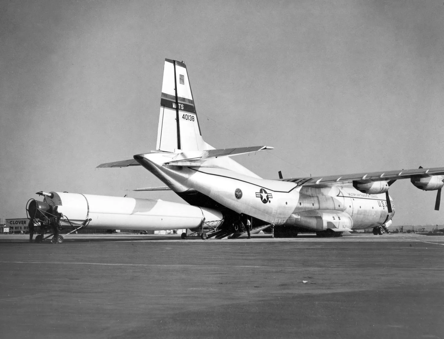


What did dual key mean?
The launch arrangements required British and American participation. RAF personnel operated the missile system while American personnel retained custody of the nuclear warhead and handled its release. Dual key describes this divided authority: neither government was intended to be able to use the force independently.
The physical keys were part of an arrangement that also depended on authenticated orders and the two governments’ decisions. Technical preparation, permission to proceed and actual launch were different stages of responsibility. Raising a missile or increasing its alert state did not itself mean that a political order to fire had been given.
This distinction is particularly important when reading memories of October 1962. An officer could describe a missile as ready while still waiting for the authority that would permit its use. A short readiness time is not evidence that a launch order existed.
Sources for this passage: [1] [2] [7]- 01
British authority
RAF missile crews
British personnel operate the missile system.
- 02
American authority
US warhead custodians
American personnel retain custody of the nuclear warheads.
- 03
Joint control
Both governments must authorise
The dual-key arrangement prevents either partner acting alone.
Simplified explanatory diagram. Read the surrounding account and its sources for the conditions, chronology and limits.
Twenty stations, four groups
The network was organised around Feltwell in Norfolk, Hemswell in Lincolnshire, Driffield in Yorkshire and North Luffenham in Rutland. Each main station and its four satellites formed a five-station group: fifteen missiles per group and sixty across the deployment.
The stations reused airfields, often giving wartime sites a new purpose. The individual missile squadrons and their supporting staff therefore became part of local communities as well as a national weapons system. The base directory identifies all twenty stations, their squadrons and their groups.
Thor stood above ground. It was normally kept horizontally beneath a protective shelter and raised on an erector for launch preparations. The concrete emplacement supported fuel and power equipment, survey arrangements and blast protection. These were fixed, known positions, which limited their ability to survive an attack compared with a force that could move or disperse.
Sources for this passage: [1] [8] [5]An illustrated guide
How sixty Thor missiles were organised
Feltwell
- Feltwell — three missiles
- Mepal — three missiles
- North Pickenham — three missiles
- Tuddenham — three missiles
- Shepherds Grove — three missiles
Hemswell
- Hemswell — three missiles
- Caistor — three missiles
- Ludford Magna — three missiles
- Bardney — three missiles
- Coleby Grange — three missiles
Driffield
- Driffield — three missiles
- Carnaby — three missiles
- Catfoss — three missiles
- Full Sutton — three missiles
- Breighton — three missiles
North Luffenham
- North Luffenham — three missiles
- Folkingham — three missiles
- Melton Mowbray — three missiles
- Harrington — three missiles
- Polebrook — three missiles
Each group comprised a main station and four satellites, each with three missiles. This is an organisational diagram, not a map or a statement of readiness on a particular day.
Sources for this passage: [8]Testing and training away from Britain
The British sites were operational deployments, not test ranges. Test and training launches belonged to the American range infrastructure. Photographs of a Thor leaving a launch pad must therefore be identified by place and date rather than used as if they showed a British base firing during the crisis.
The photograph below records a test at Cape Canaveral on 12 May 1959. It illustrates the missile in flight and the scale of the exhaust, but does not establish anything about a particular RAF crew or its state of readiness in October 1962. Keeping that context visible makes the photograph useful historical evidence.
Sources for this passage: [5] [1]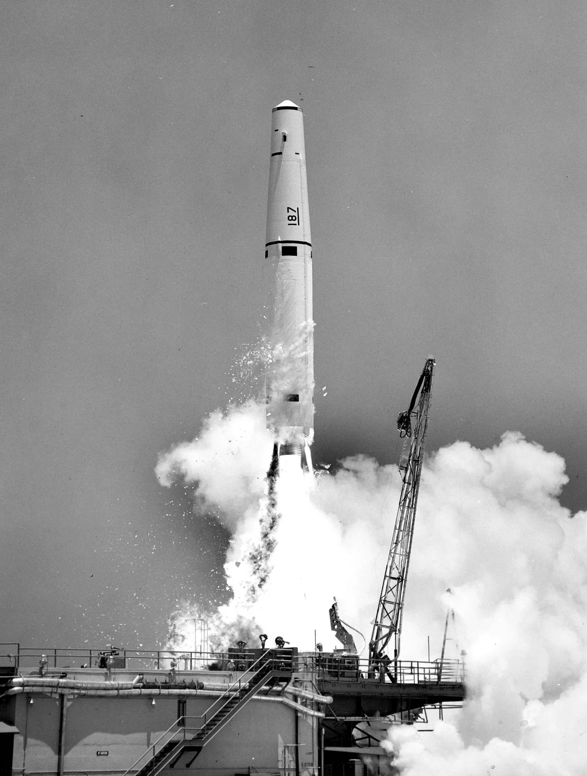


Readiness during the thirteen days
The missile crisis made an existing British deployment part of an immediate confrontation. By 27 October, the RAF Air Power Review account reports 59 of the 60 Thors at fifteen minutes’ readiness. It also notes evidence that some missiles were held at a more advanced stage of preparation. These are descriptions of readiness, not statements that the missiles were fired or that their crews had authority to begin a war.
The same account places Thor alongside the heightened readiness of the V-bomber force. Britain’s exposure therefore extended beyond the missile bases: aircraft, nuclear weapons, communications and political decisions were all part of the response. American DEFCON terminology should not simply be pasted onto every British unit.
For the crews, a crisis that appeared to the public as speeches and diplomatic exchanges also meant maintaining a complex system under increased tension. The distinction between routine duties, alert preparation and a genuine launch order is essential when interpreting later recollections of those days.
Sources for this passage: [9] [7]Why Thor left Britain in 1963
Thor was an interim system, and its withdrawal was already being discussed before October. Fixed positions, the need for extensive ground support and changes in the wider deterrent all form part of that longer history. The British force closed during 1963.
This must be distinguished from the private American assurance about Jupiter missiles in Turkey that helped settle the crisis. Thor was not the British half of that secret exchange. The two withdrawals can look similar on a timeline while having different decision histories.
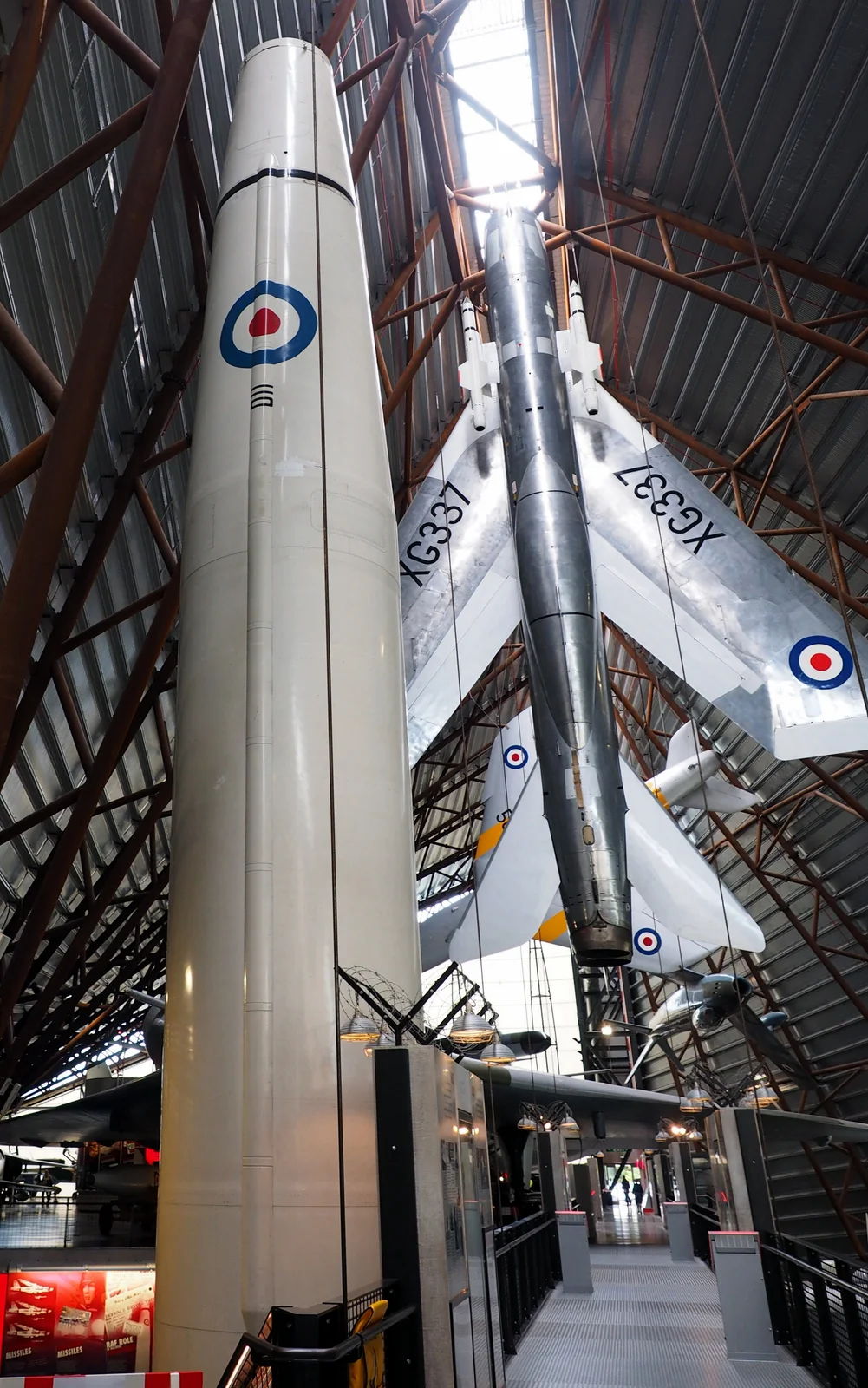
The end of the British missile force did not end every use of Thor technology. The rocket’s development also belongs to the history of American space launchers. A museum specimen or a later launch photograph may therefore represent a different chapter from the RAF deployment.
Sources for this passage: [1] [10] [3]What survives in the landscape?
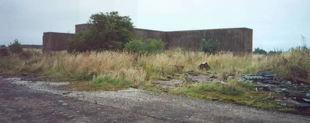
At Harrington, the surviving concrete and blast walls make the scale of the deployment tangible. Historic England records three emplacements, the launch-control area and protected storage buildings. Its detailed account explains how the remains relate to the former missile station.
North Luffenham and Polebrook provide other evidence of the Thor landscape. The base map uses approximate station locations for historical orientation. Surviving structures and museum displays help explain the system, but a historic listing or a map marker does not establish current public access.
The photographs below are explicitly dated 2000 and 2022. One records surviving structures at Harrington; the other shows a preserved missile at RAF Museum Midlands. They complement the period photographs without pretending to show the bases as crews saw them in October 1962.
Sources for this passage: [2] [8] [11]